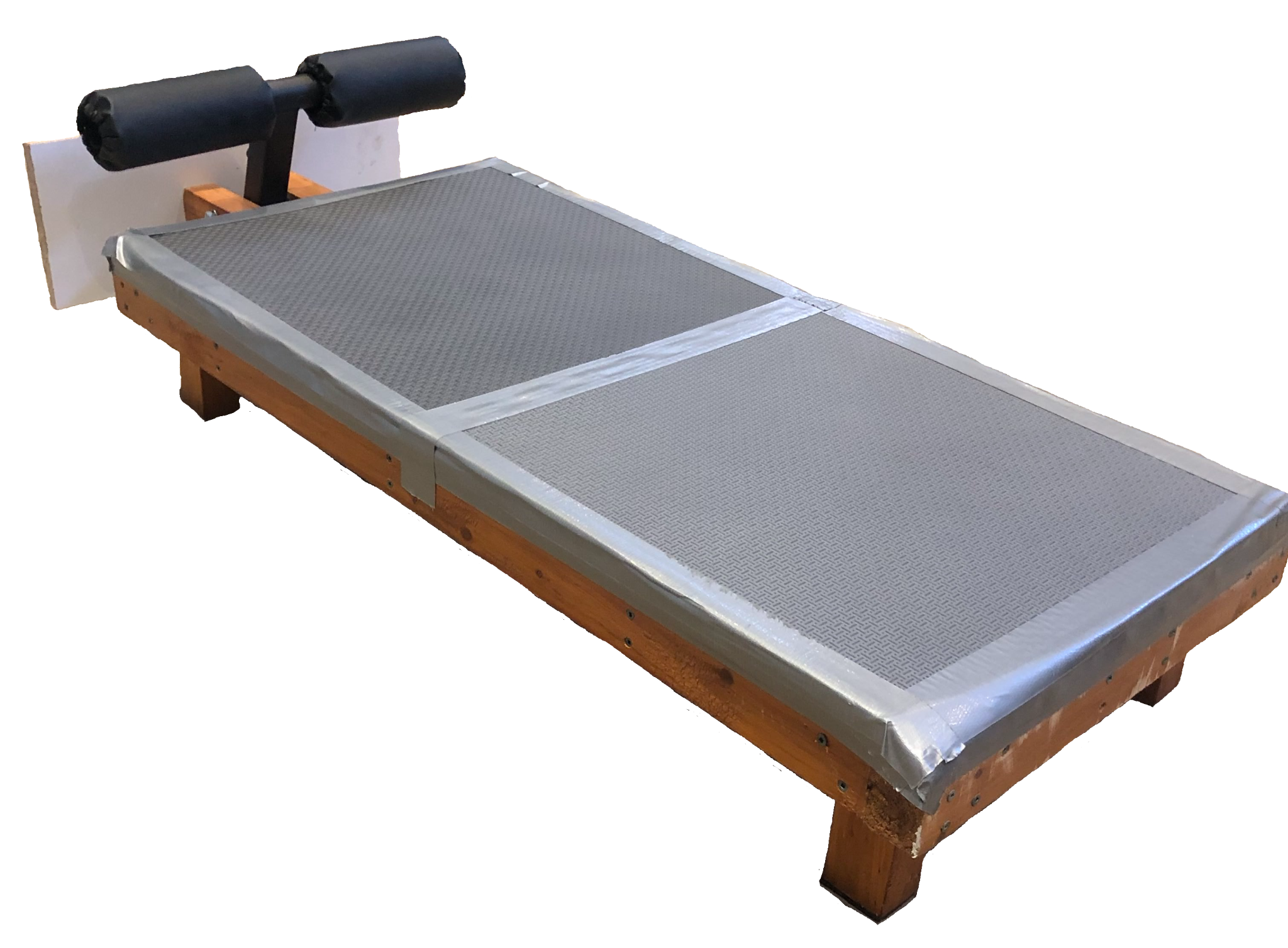
BTP-01
Active Suspension: Phase 2
BUILT IT FOR REAL AUG 2026
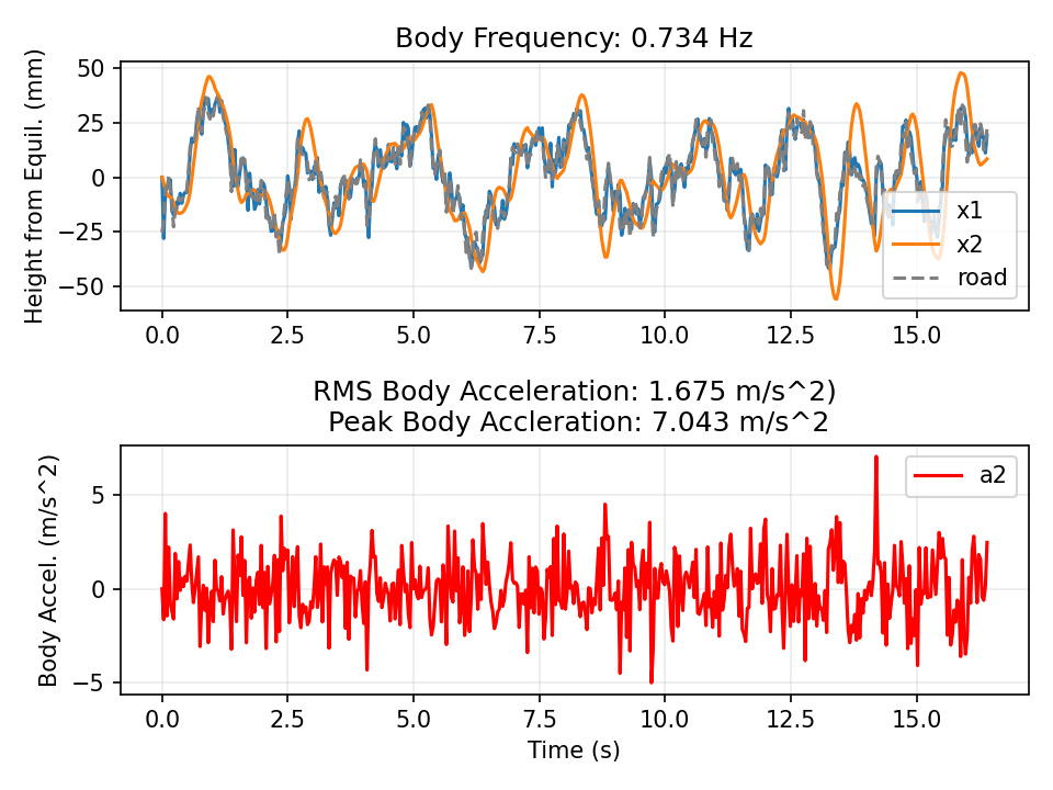
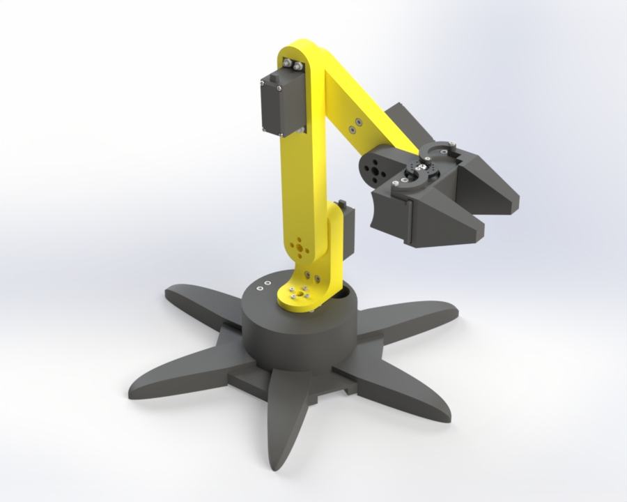
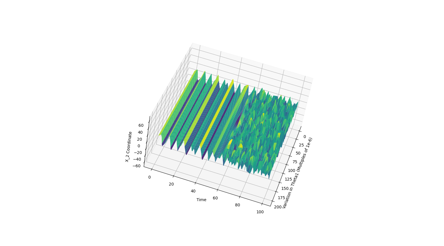
FIGURES IN PAGE ORDER 01 → 02
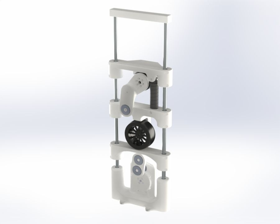
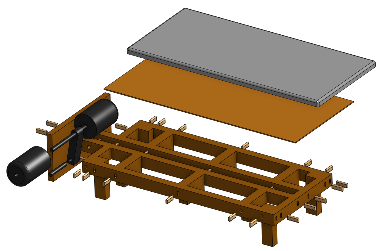
Against the motor's 2 Nm stall that allows an arm up to 588 mm, which is absurdly long. The real limit was not torque but cogging: a longer arm multiplies the motor's cogging torque through the whole system, so I chose the shortest practical arm, 50 mm. That choice is exactly what came back to bite me.
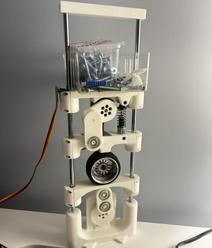
Then I measured the sag from the top of the travel versus the bottom and got a 1.5 to 2 mm band. That gap is friction, and it was large. Removing the actuator collapsed the band to about 5 mm of clean travel, which located the culprit: the motor's cogging torque, multiplied along that 50 mm arm, was fighting the suspension the whole way.
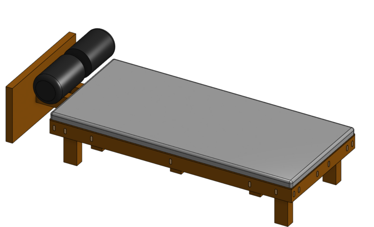
GENERAL VIEW HERO
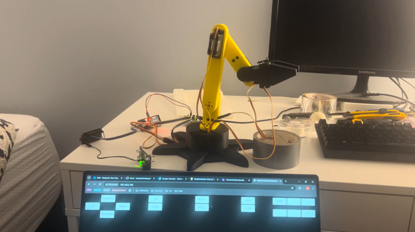
THE RIG RUNNING / 3 HZ ROAD, DROP TEST, PUSH DOWN AND PULL UP
GENERAL NOTES / HOVER A FIGURE FOR ITS PASSAGE
- Phase 1 proved skyhook control in simulation. Phase 2 was meant to build that quarter-car model in hardware and run the controller for real. I built the rig. The controller never ran: friction and motor cogging overdamped the system, and skyhook is undefined on an already-overdamped plant. This page is the honest version of that, because the build is where I learned the most.
- The plan was six steps: spec a BOM, test the parts, CAD the rig, port the phase 1 math to a real controller, run it on generated roads, and compare against the sim. I got through the rig. The physics of a small rig stopped me at the controller.
TOOLS SolidWorks3D PrintingDirect-Drive MotorIMUHardware
DRAWN BY
Benjamin Tran-Pugh
Mechanical engineering, University of Waterloo
SHEET
01 / 08
benjamintranpugh@gmail.com btranpug@uwaterloo.ca github.com/BenjaminTP
linkedin.com/in/benjamin‑tran‑pugh
resume →
DWG
BTP-01
FIGS
03
DIMENSIONS IN MM / TOLERANCES ±0.5 UNLESS NOTED / DO NOT SCALE DRAWING