Overview
I built a quarter-car suspension model from scratch to answer one question: how much ride comfort can an actuator buy you over a passive spring and damper? Comfort is measured as RMS body acceleration, so that is the number I optimized and the number I report.
Skyhook control cut it on every road I tested.
Phase 1 consists of: derivation, parameter selection, control law, road generation, and a test bench. Phase 2 adds a physical model.
The model
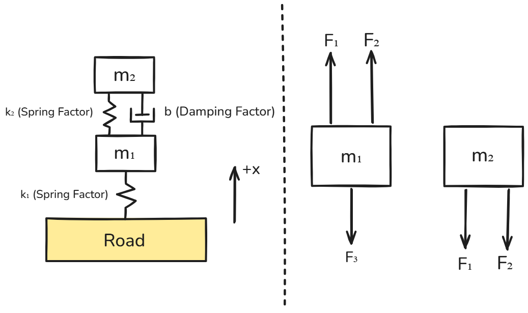
Most derivations I found waved away gravity, so I worked the equations of motion out from first principles instead. Writing the spring forces in absolute coordinates, then substituting each mass’s static equilibrium position, makes the
Picking the parameters
I sized a quarter of a 1500 kg car, then worked backwards from the ride frequency Fundamentals of Vehicle Dynamics (Gillespie) gives as comfortable, 1.0 to 1.5 Hz. Choosing 1.2 Hz and a 225 kN/m tire fixes the spring through the ride rate
| Parameter | Value | Where it came from |
|---|---|---|
| Body mass | 375 kg | quarter of a 1500 kg car |
| Wheel mass | 30 kg | typical wheel assembly |
| Tire stiffness | 225 kN/m | midpoint of the 150 to 300 kN/m range |
| Spring stiffness | 23.55 kN/m | solved from 1.2 Hz ride frequency |
| Damping | 1783 N s/m | damping ratio 0.3 (Gillespie, p.148) |
The check on the parameters is the wheel hop frequency, which I never chose directly: it falls out at 14.5 Hz, inside Gillespie’s 10 to 15 Hz band. Simulating a body release then measured 1.175 Hz against the 1.2 Hz I designed for, a 2.1% error, which told me the solver and the hand calculations agreed.
Skyhook control
Skyhook pretends the body hangs from a damper anchored to the sky, so the actuator fights the body’s absolute velocity rather than suspension travel. As an internal force pair it adds one term to each equation and cancels when you sum them, which is a useful sanity check that no energy is being invented.
Targeting an effective damping ratio of 0.7 leaves the actuator responsible for the difference between that and the passive damper:
In the solver that is two lines:
def deriv(t, y):
    x1, x2, v1, v2 = y
    F_a = -C_SKY * v2
    a1 = (K2*(x2 - x1) + B*(v2 - v1) - K1*(x1 - road(t)) - F_a) / M1
    a2 = (-K2*(x2 - x1) - B*(v2 - v1) + F_a) / M2
    return [v1, v2, a1, a2]
Sizing the actuator by hand at resonance, with a 20 mm body amplitude, gives a peak of 328 N. The test bench later put the real worst case at 663 N, so the hand calculation was the right order of magnitude but not a spec I would have ordered hardware against.
Generating real roads
A step or a cosine bump is not a road. The ISO 8608 standard describes real surfaces by their power spectral density, and the useful result is that measured road PSDs fall on a straight line of slope
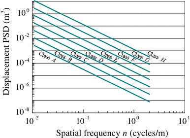
Power of an arbitrary sine wave
To turn that curve into an actual surface I needed the amplitude of each wave, and the link is that the power a wave carries is its variance. So I derived the variance of a general sine wave, where
The phase drops out entirely, which is what makes this usable: every wave contributes
Building the surface
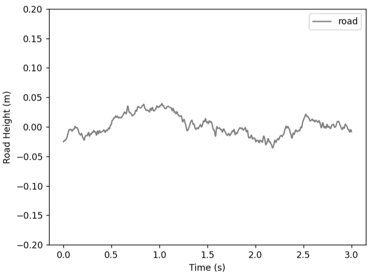
Summing 1000 waves across 0.01 to 2 cycles/m then gives the profile:
Each wave gets a random phase
Test bench
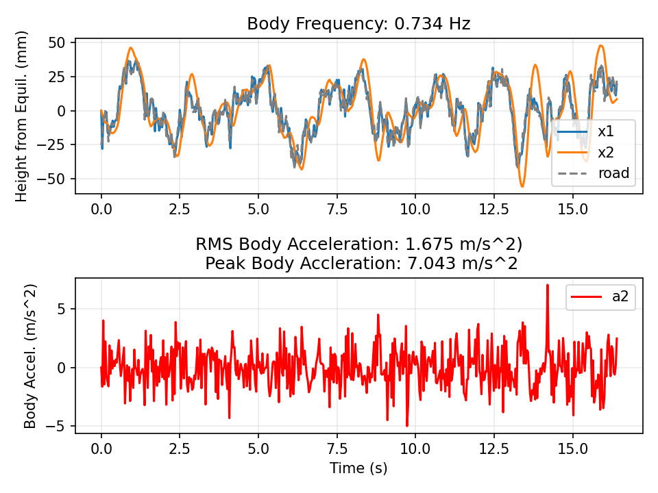
Lowering RMS acceleration is easy if you ignore what it costs. The bench therefore logs the three quantities that size real hardware alongside comfort: peak suspension travel, peak tire deflection, and peak actuator force.
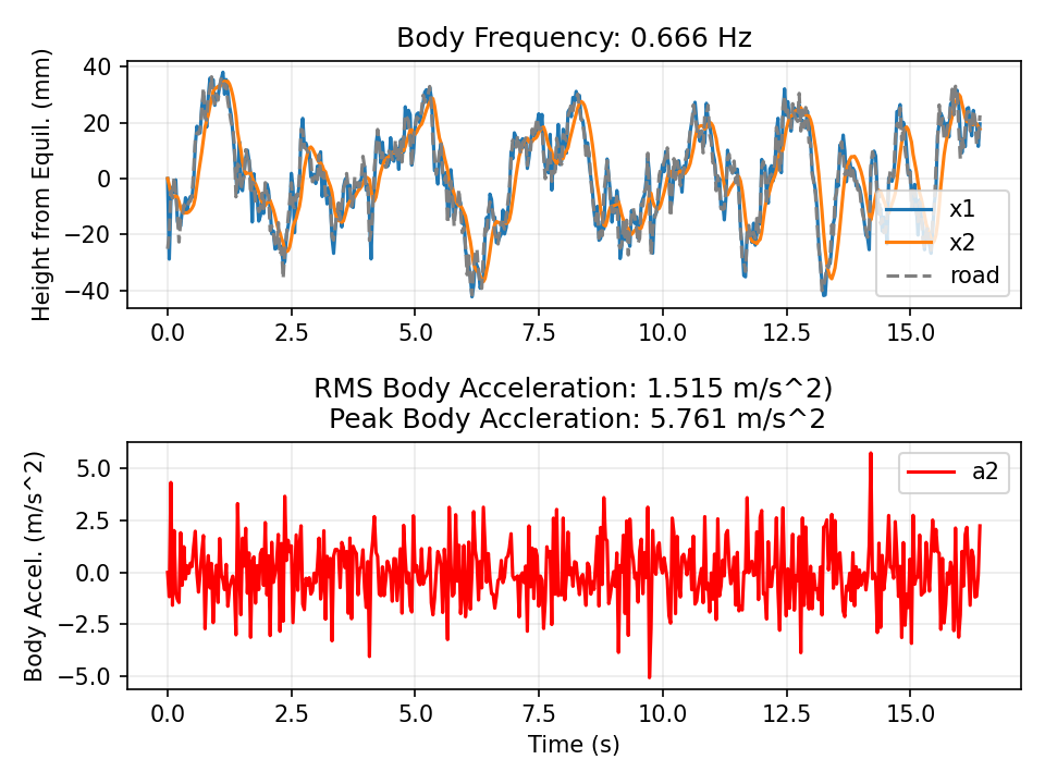
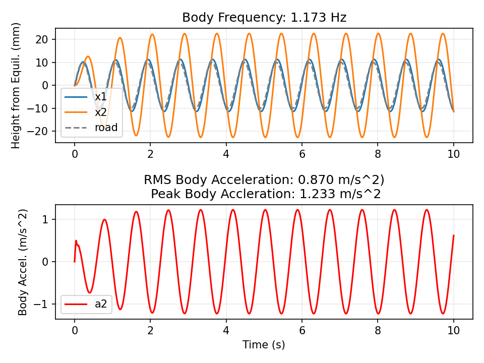

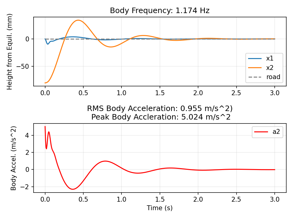
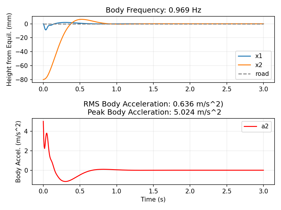
| Road case | RMS accel. | Peak accel. | Susp. travel | Tire deflect. | Peak force |
|---|---|---|---|---|---|
| Class C, 100 km/h | -9.6% | -18.2% | -18.2% | -5.2% | 467 N |
| 5 cm bump | -12.3% | -0.9% | +7.5% | -1.8% | 559 N |
| Body released 8 cm down | -37.6% | -24.2% | -1.3% | -7.0% | 663 N |
| Resonance road | -57.1% | -57.2% | -45.6% | -56.1% | 156 N |
The result I did not expect is that comfort mostly came for free. Textbook suspension design treats ride and handling as a trade, but skyhook improved tire deflection in all four cases and suspension travel in three of them. The single penalty is 7.5% more suspension travel over the 5 cm bump, and it is worth knowing: on a discrete obstacle the actuator pushes the body up rather than letting the spring absorb the hit, so the stroke has to be there in the hardware.
Gains are largest at resonance, which makes sense. That is where a passive damper is doing its worst work and where the skyhook term is most directly opposed to the motion.
Watching it move
Body in orange, wheel in blue, road in grey. Passive on top, skyhook below, driving the same profile at the same speed.
Draw your own road
This is an interactive version of the same model: draw a road profile in the lower panel and watch both suspensions drive it, with live RMS and actuator readouts. I had not built an animation before, so I gave Claude my parameters and derivations and had it write the front end. The physics and the numbers are mine; the interface is not my work.
What is next
Phase 1 only implements skyhook. Phase 2 gives the theory a body.
This page is the summary. I wrote a full Phase 1 writeup that carries every step at length: the equations of motion derived line by line, why each parameter was chosen and checked against Gillespie, the complete ISO 8608 and variance derivations, and all eight benchmark cases with their plots. If you want to see how I actually work through a problem, read that.