Overview
Phase 1 proved skyhook control in simulation. Phase 2 was meant to build that quarter-car model in hardware and run the controller for real. I built the rig. The controller never ran: friction and motor cogging overdamped the system, and skyhook is undefined on an already-overdamped plant. This page is the honest version of that, because the build is where I learned the most.
The plan was six steps: spec a BOM, test the parts, CAD the rig, port the phase 1 math to a real controller, run it on generated roads, and compare against the sim. I got through the rig. The physics of a small rig stopped me at the controller.
The build
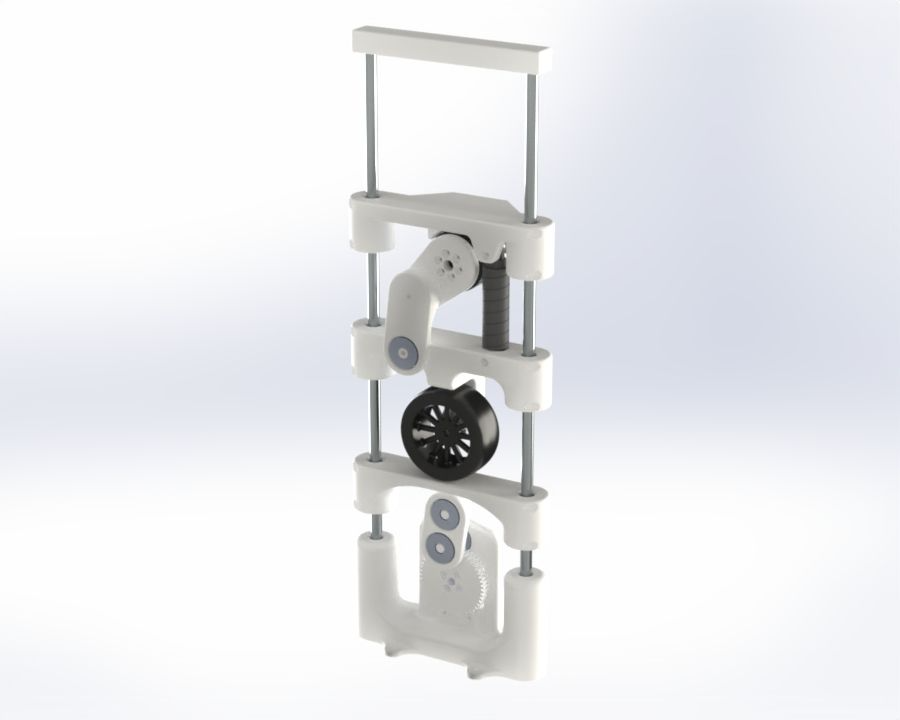
I needed every element of the phase 1 model as a physical part, constrained to move only vertically on linear rails. The piece with no obvious answer was the road: I turned a servo through a crank and pushrod to convert rotation into vertical travel, and used the same trick for the skyhook actuator.
The actuator drove the parts list. Skyhook needs a motor that is fully back-driveable with torque control, which rules out anything geared and leaves direct drive or quasi-direct drive. I took the cheaper direct-drive path with a Damiao DM-H6215: 1 Nm nominal, 2 Nm stall, torque control, and $59. The rest was deliberately cheap: an RC buggy wheel, an RC coilover for the passive spring and damper, an MPU6050 for body acceleration, and a bin of scrap metal for the body mass.
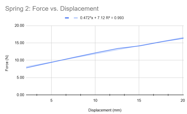
Then reality set the parameters instead of me. Of the locked values from phase 1, only
Sizing it in CAD
Two numbers had to be right before modelling: the two moment arms that convert motor rotation into force.
Scaling a real bump down to this rig, a 3” bump on a 25” tire maps to about 8 mm on the 66 mm wheel, which fits inside the 19.6 mm of suspension travel. So the road crank needed a 4 mm arm for 8 mm of total throw.
The actuator arm came from peak force. Using the phase 1 result that peak body velocity is
With upper-bound parameters (
Against the motor’s 2 Nm stall that allows an arm up to 588 mm, which is absurdly long. The real limit was not torque but cogging: a longer arm multiplies the motor’s cogging torque through the whole system, so I chose the shortest practical arm, 50 mm. That choice is exactly what came back to bite me.
The turn
I printed the parts, wired the electronics, sized the body mass to sit at mid-travel (
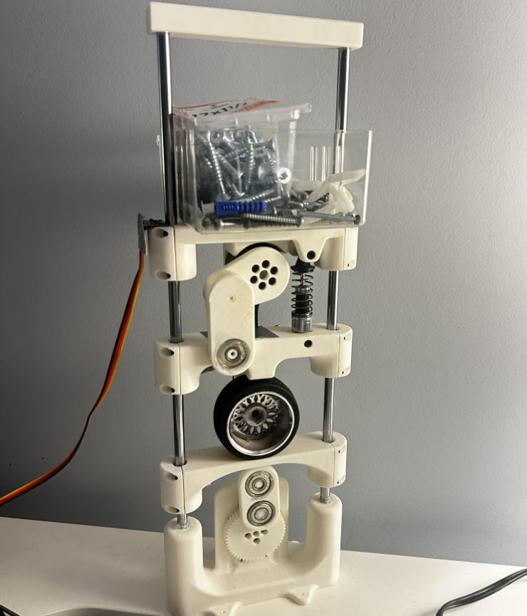
Then I measured the sag from the top of the travel versus the bottom and got a 1.5 to 2 mm band. That gap is friction, and it was large. Removing the actuator collapsed the band to about 5 mm of clean travel, which located the culprit: the motor’s cogging torque, multiplied along that 50 mm arm, was fighting the suspension the whole way.
On a rig this small, those friction and cogging forces land on the same order as the suspension forces themselves. That overdamps the system, and skyhook has nothing to do on an overdamped plant (phase 1 covers why). A drop test, a hold-and-release, and a 3 Hz road all showed textbook overdamped behavior: the body eases back to rest with no overshoot, no oscillation for the controller to cancel.
What I would change
The fix is scale. A physically larger rig pushes the suspension forces well above the fixed friction and cogging, so they stop dominating. Failing that, a lower-cogging actuator and smoother linear and ball bearings would buy back the same margin at this size. Both cost more than a first physical prototype was worth.
I did not get skyhook running on hardware, and I am not going to pretend otherwise. What I got was the part that does not show up in a simulation: where the model quietly assumes an ideal, and how to design around hardware that refuses to be ideal. The full parts list, measurements, and derivations are in the Phase 2 writeup.